Not known Details About Wedge Barriers
Table of ContentsAn Unbiased View of Wedge BarriersExcitement About Wedge Barriers

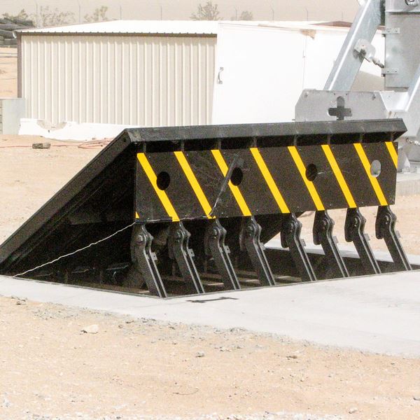
18 might be done faster, quickly, and cost effectively. FIG. In particular embodiments, the anchor 30 might be a steel framework including plates, beam of lights(e. g., I-beams ), and/or other structures that are safeguarded within the structure 14, which may be concrete. At the surface 12, a top side 28 of the support 30 might go to least partially revealed
, therefore making it possible for the add-on of the barrier 10 to the support 30. g., threaded holes)in several beam of lights or plates of the anchor 30 might be subjected to the surface 12. In this manner, screws 32 or various other mechanical fasteners might be utilized to protect the barrier 10 to the support 30. As the barrier 10 is mounted to the surface 12 of the structure 14, collection of debris and other product below the obstacle might be minimized, and components of the bather 10 may not be revealed to below grade settings. As suggested by referral numeral 52, the lifting device 50 includes components got rid of beneath the wedge plate 16. The elements 52 underneath the wedge plate 16 may include an electromechanical actuator, a camera, one or even more webcam surfaces, and so forth. In addition, the training mechanism 50 includes a spring assembly 54
The spring pole 58 is paired to a web cam(e. g., cam 80 received FIG. 4) of the lifting system 50. The springs 60 disposed about the spring rod 58 are held in compression by spring supports 62, including a dealt with spring support 64. That is, the fixed spring support 64 is dealt with about the foundation 14 et cetera of the bather 10.
Wedge Barriers Things To Know Before You Buy
The continuing to be pressure used to
the cam web cam deploy release wedge plate 16 may might provided by an electromechanical actuator 84 or other various other. The springtime assembly 54 and the actuator 84(e. Wedge Barriers. g., electromechanical actuator)may run together to convert the camera and lift the wedge plate 16.
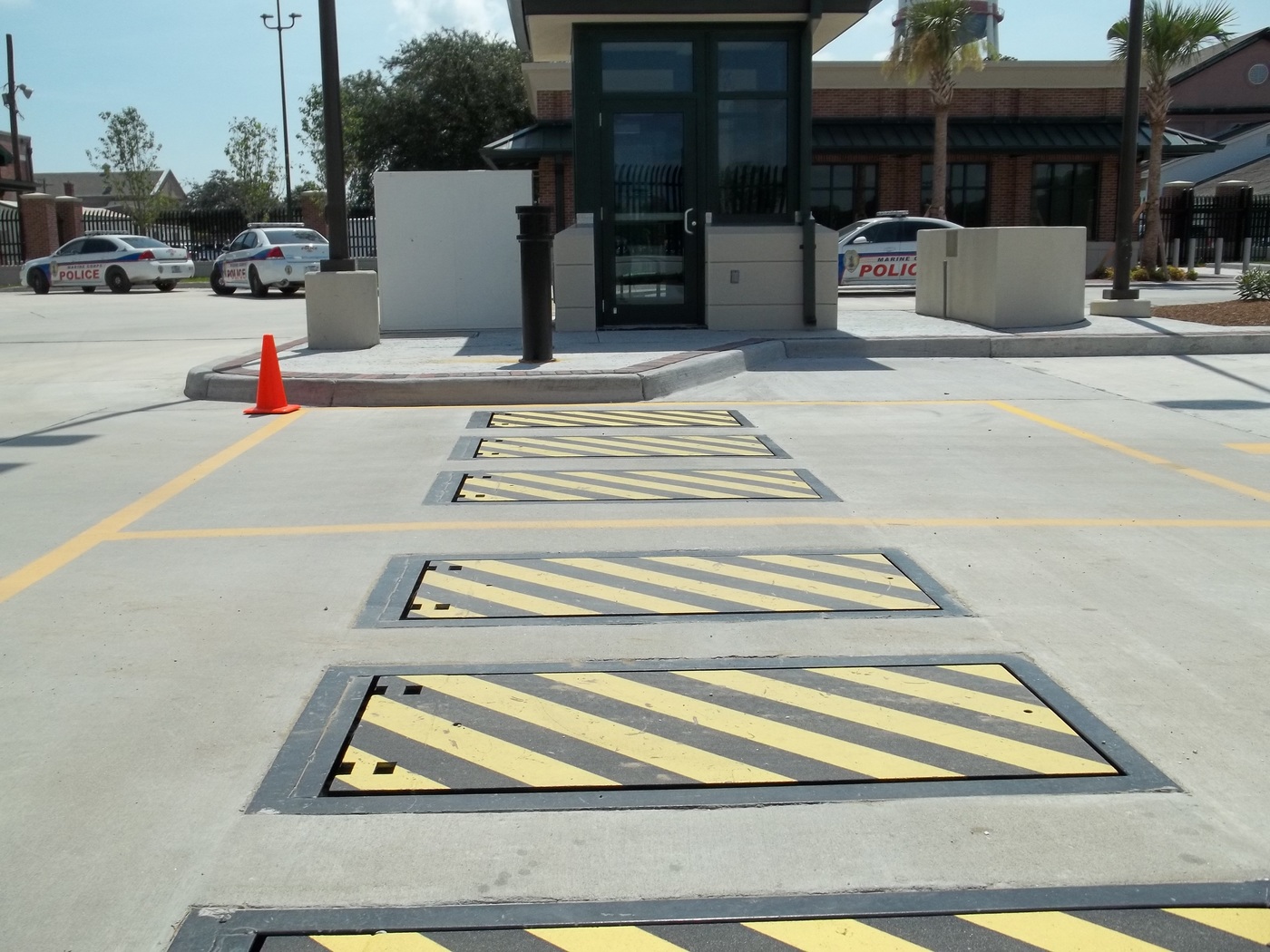
As discussed over, the spring setting up 54 applies a constant force on the webcam, while the electromechanical actuator might be controlled to exert a variable pressure on the camera, thus click site making it possible for the training and decreasing( i. e., releasing and pulling back )of the wedge plate 16. In particular personifications, the continuous pressure used by the spring setting up 54 might be flexible. g., electromechanical actuator) is impaired. As will certainly be valued, the springtime setting up 54 may be covered and secured from particles or other components by a cover plate(e. g., cover plate 68 displayed in FIG. 4) that may be substantially flush with the elevated surface area 38 of the structure 14. As pointed out over, in the deployed placement, the wedge plate 16 offers to block gain access to or travel beyond the obstacle 10. The obstacle 10(e. g., the wedge plate 16 )may block pedestrians or lorries from accessing a residential or commercial property or path. As gone over above, the obstacle 10 is connected to the support 30 secured within the foundation 14,
front brackets 71. Therefore, the affiliation settings up 72 may pivot and rotate to make it possible for the collapse and extension of the affiliation settings up 72 during retraction and deployment of the bather 10. The linkage settings up 72 cause movement of the wedge plate 16 to be limited. If a lorry is traveling in the direction of the released wedge plate 16(e. For instance, in one condition, go to my site the safety legs 86 may be extended throughoutmaintenance of the barrier 10. When the safety and security legs 86 are released, the security legs 86 sustain the weight of the wedge plate 16 versus the surface 12. Therefore, the lifting system 50 might be shut down, serviced, gotten rid of, changed, and so forth. FIG. 5 is partial viewpoint sight of a personification of the surface-mounted wedge-style obstacle 10, showing the cam 80 and the webcam surface areas 82 of the training system 50. Especially, two web cam surfaces 82, which are described as lower cam surface areas 83, are positioned below the web cam 80. The lower webcam surfaces 83 might be dealt with to the surface area 12 (e. As an example, the lower webcam surface areas 83 and the installing plate 85 might form a single piece that is secured to the anchor 30 by screws or other mechanical fasteners. Furthermore, 2 web cam surfaces 82, which are referred to as top webcam Related Site surface areas 87, are placed over the webcam 80 and paired to (e. In various other embodiments, intervening layers or plates might be placed in between the surface area 12 and the reduced web cam surface areas 83 and/or the wedge plate 16 and the top webcam surfaces 87 As discussed above, the webcam
80 converts along the web cam surface areas 82 when the wedge plate 16 is lifted from the withdrawed placement to the deployed placement. Furthermore, as stated over, the spring setting up 54 (see FIG. 3 )may offer a pressure acting on the camera 80 in the direction 102 using springtime pole 58, which might reduce the pressure the electromechanical actuator 84 is called for to use to the camera 80 in order to activate and lift the wedge plate 16. 1 )to the deployed setting(see FIG. 4). As revealed, the web cam 80 includes track wheels 104(e. g., rollers), which contact and translate along the webcam surfaces 82 during procedure.